

+86 18911081735

31.5 MPa nominal pressure 1.25–400 ml/r displacement 8 control types 1000 / 1500 r/min rated speed Product Advantages Every unit is built around the same proven rotating-group design, so a single spar…
Inquire NowEvery unit is built around the same proven rotating-group design, so a single spare-parts stock covers the whole range.
Oil-film balancing between slipper and swash plate, and between valve plate and cylinder block, keeps friction and wear low.
Precision-lapped valve plate and cylinder face hold leakage to a minimum across the full pressure range.
High power-to-weight ratio and a short overall length make the pump easy to fit inside existing machine frames.
Handles suction lifts up to 500 mm and can be mounted above or beside the reservoir without a charge pump.
Fitting a motor-type port plate converts the pump into a hydraulic motor without changing the housing.
Fixed, manual, pressure-compensated, two-stage, proportional, constant-pressure, servo and electric variants share one mounting footprint.
Example: 160YCY14-1B — 160 ml/r, pressure-compensated variable pump, 31.5 MPa, rotating cylinder block design, first structure version.
| Code | Meaning | Options |
|---|---|---|
| 160 | Nominal displacement | 1.25, 2.5, 5, 10, 16, 25, 32, 40, 63, 80, 160, 250, 400 ml/r |
| Y | Variable type | M fixed · S manual · Y pressure compensation · MY two-stage · B electro-hydraulic proportional · P constant pressure · C servo · D electric |
| C | Pressure class | C = 31.5 MPa |
| Y | Pump or motor | Y = pump · M = motor |
| 14 | Structure code | Rotating cylinder block axial piston pump |
| 1 | Structure version | First structure version |
| B / G | Design index | B standard · G = 1500 r/min speed-up version (160 and 250 only) |
| F | Direction of rotation | No mark = clockwise (viewed from shaft end) · F = anti-clockwise |
Select the prefix that matches the way the machine needs to use flow and pressure.
| Prefix | Type | Behaviour | Typical application |
|---|---|---|---|
| MCY | Fixed displacement | Constant flow at constant speed; no variable mechanism | Simple circuits, lowest cost |
| SCY | Manual variable | Handwheel turns the adjusting screw and moves the stroke piston; lock nut holds the setting | Test stands, infrequent flow changes |
| YCY | Pressure compensation | Flow follows a constant-power curve as pressure rises; adjustable cut-in pressure | Injection moulding, presses — protects the drive motor |
| MYCY | Two-stage variable | Full flow below 3–4 MPa, then steps down to the high-pressure flow | Fast approach followed by a working stroke |
| BCY | Electro-hydraulic proportional | Flow proportional to solenoid current; 150–250 mA dead band, 650–800 mA maximum, 6–12 MPa pilot oil | Closed-loop control, remote and programmed sequences |
| PCY | Constant pressure | Holds the set pressure and delivers only the leakage at pressure; stepless setting | Clamping, holding, accumulator charging |
| CCY | Servo variable | Mechanical or lever signal drives the stroke piston | Machine-tool feed, linkage control |
| DCY | Electric variable | Motor-driven adjustment of the swash-plate angle | Automated setting, remote trimming |
Note: on BCY units the inlet and outlet ports are positioned opposite to those of the other control types at the same direction of rotation. Check the port layout before piping.
Theoretical values at 31.5 MPa, without mechanical-hydraulic and volumetric losses. Every displacement is available in all eight control types — for example 63YCY14-1B or 63SCY14-1B.
| Displacement | Flow at 1000 r/min | Flow at 1500 r/min | Max. drive power | Max. torque |
|---|---|---|---|---|
| 2.5 ml/r | 2.5 L/min | 3.75 L/min | 1.43 kW | 17.5 N·m |
| 10 ml/r | 10 L/min | 15 L/min | 5.7 kW | 54.6 N·m |
| 25 ml/r | 25 L/min | 37.5 L/min | 14.1 kW | 134.9 N·m |
| 40 ml/r | 40 L/min | 60 L/min | 22.6 kW | 201.5 N·m |
| 63 ml/r | 63 L/min | 94.5 L/min | 35.6 kW | 339.9 N·m |
| 80 ml/r | 80 L/min | 120 L/min | 46.6 kW | 405.1 N·m |
| 160 ml/r | 160 L/min | 240 L/min | 92.2 kW | 880.3 N·m |
| 250 ml/r | 250 L/min | 375 L/min | 133.2 kW | 1272.4 N·m |
| 400 ml/r | 400 L/min | 600 L/min | 199.5 kW | 1905.2 N·m |
Also available as derived displacements at 31.5 MPa: 1.25, 5, 16 and 32 ml/r. Drive power N = Q × P / (60 × η); overall efficiency η may be taken as 0.85 for motor selection.
The rotating group is carried by a large front bearing and a small rear bearing, with the swash plate mounted in the variable housing. The numbered callouts below refer to the parts list underneath the drawing.
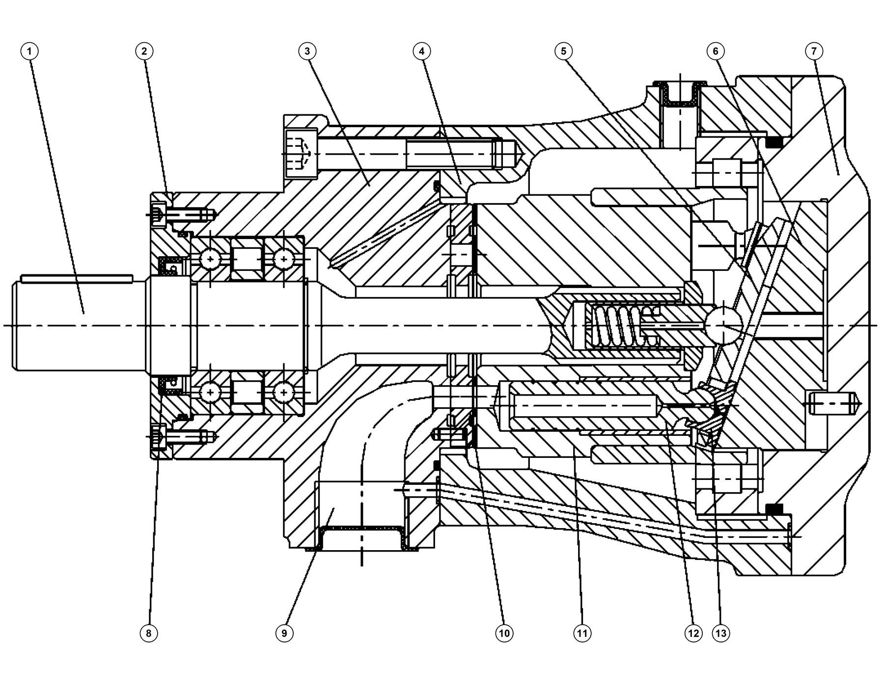
Figure 1 — Section through the CY14-1B rotating group and variable housing.
1 Drive shaft
2 Mounting flange
3 Pump body
4 Housing
5 Retainer plate
6 Swash plate
7 End cover
8 Shaft seal
9 Inlet / outlet port
10 Valve plate
11 Cylinder block
12 Plunger
13 Slipper
Supplied as original equipment to machine builders and as a drop-in replacement for installed CY14 units.
Most field failures trace back to coupling alignment or oil cleanliness, so both are worth checking before commissioning.
The CY-Y series combines a CY14-1B pump with a Y-series asynchronous motor, removing the coupling and bracket and cutting the installed length by one third.
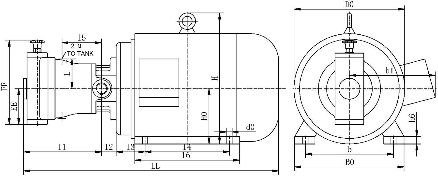
Figure 2 — CY-Y pump-motor group, Y-series motor with B3 foot mounting.
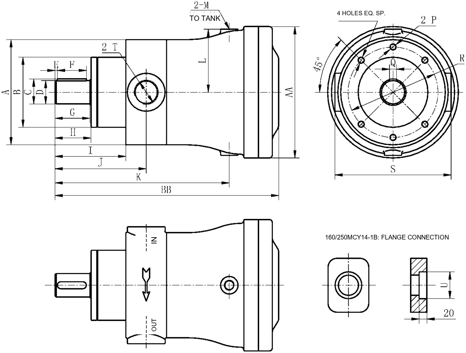
Figure 3 — MCY14-1B mounting dimensions. The lower view shows the inlet and outlet ports with flow arrows; the 160 and 250 sizes use a flange connection.
The HY series shares the same mounting and port dimensions but adds P01–P05 energy-saving control modes, a 320 ml/r top end and a higher peak pressure. It is a direct replacement for most installed CY14-1B units.
| CY14-1B | HY | |
|---|---|---|
| Displacement | 1.25–400 ml/r | 10–320 ml/r |
| Pressure | 31.5 MPa | 315 bar, 400 bar peak |
| Control types | 8 | 11, incl. P01–P05 |
| Mounting and ports | Reference | Identical |
| Hydraulic motor use | Yes | No |
The questions we are asked most often when customers specify a replacement unit.
The prefix is the control type. MCY is fixed displacement, SCY is manual, YCY is pressure compensated for constant-power operation and PCY holds a constant pressure. Match it to how the machine uses flow and pressure.
Yes. Fitting a motor-type port plate converts the unit to a hydraulic motor; the housing and rotating group are unchanged.
Clockwise viewed from the shaft end. Add the suffix F for anti-clockwise rotation — note that the inlet and outlet positions swap with it.
In most cases yes. The mounting flange and port dimensions are identical, and the HY adds P01–P05 energy-saving controls with a higher peak pressure. Confirm the control type before ordering.
L-HM 32, 46 or 68 anti-wear oil, 15–65 °C, operating viscosity 27–43 mm²/s and cleanliness of NAS 10 (19/16) or better.
Yes. Valve plates, plungers, slippers, cylinder blocks and complete rotating groups are stocked, and the pump can be supplied as a CY-Y pump-motor group.
Send us the displacement, working pressure and control type you need, or a photo of the nameplate, and we will confirm the exact model within one working day.
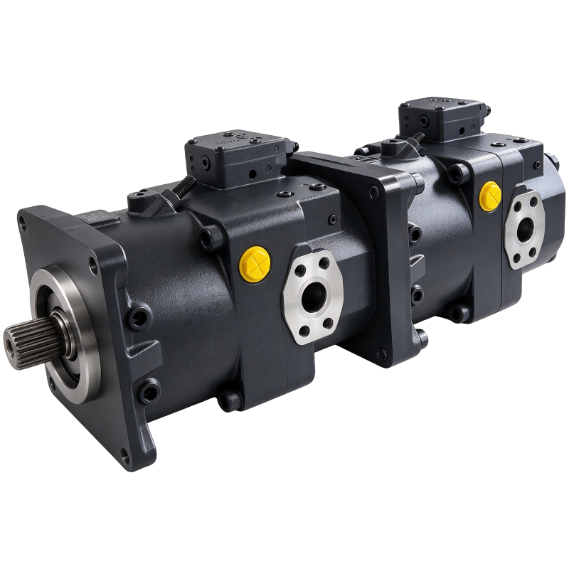
A11V
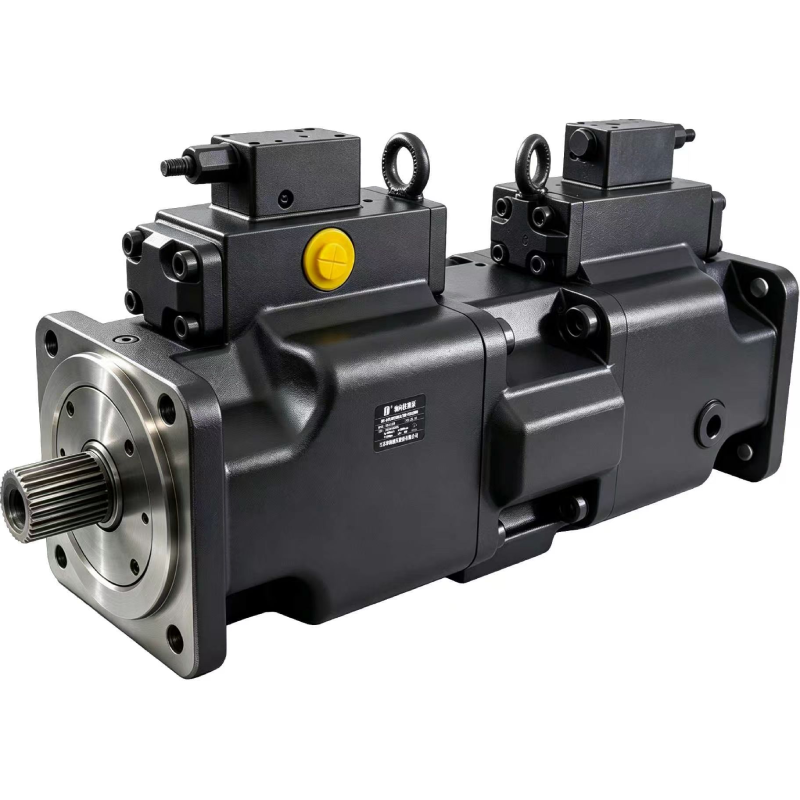
A4VLODT
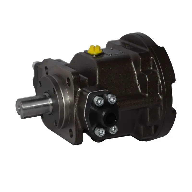
HY-M Quantitative
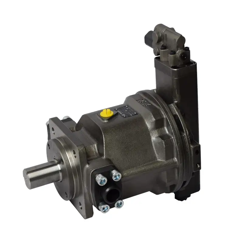
HY-P constant pressure