

+86 18911081735
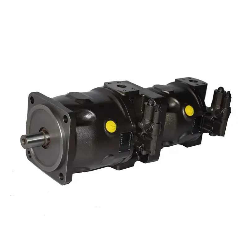
Overview Heavy-duty performance in a compact envelope The JA10VSO/32 is a swashplate-type axial piston variable pump designed for open circuits. Its rotating group, controller and housing are engineer…
Inquire NowThe JA10VSO/32 is a swashplate-type axial piston variable pump designed for open circuits. Its rotating group, controller and housing are engineered as one system: pressure up to 280 bar continuous, 350 bar peak and 315 bar intermittent (10% duty cycle) are available across all five sizes, so the same family covers everything from a 45 cm³ mobile circuit to a 180 cm³ industrial power unit.
Three mounting-flange options, four shaft ends, six service-port patterns and seventeen through-drive variants keep the installation work simple — and allow a second pump or a gear pump to be flange-mounted without an extra coupling.
Up to 802 N·m of torque at Vg max and 324 L/min flow at 1800 rpm — the 180 size replaces larger, heavier units.
Pressure, remote pressure, pressure/flow, and pressure/flow/power control with adjustable cut-off — matched to the duty cycle of your machine.
Seventeen through-drive codes (ISO and SAE flanges) for tandem pumps or a flange-mounted gear pump — no extra bell housing required.
Nitrided and hardened critical components — heat-treated in house — keep performance stable through long duty cycles at rated pressure.
Controllers and shaft seals are available as separate service parts, so a repair on site does not mean replacing the whole pump.
ISO 3019-2/1 and SAE flanges, metric and SAE shafts, SAE straight-thread or UNC ports — configured per order, not per stock.
| Parameter | 45 | 71 | 100 | 140 | 180 |
|---|---|---|---|---|---|
| Displacement Vg maxcm³/rev | 45 | 71 | 100 | 140 | 180 |
| Max. speed nmaxrpm | 1800 | 1800 | 1800 | 1800 | 1800 |
| Max. flow at nmaxL/min | 81 | 128 | 180 | 252 | 324 |
| Max. flow at 1500 rpmL/min | 67.5 | 106.5 | 150 | 210 | 270 |
| Max. power at nmaxkW · Δp = 280 bar | 38 | 59.7 | 84 | 118 | 151 |
| Max. power at 1500 rpmkW · Δp = 280 bar | 31 | 50 | 70 | 98 | 125 |
| Max. torque TmaxN·m · at Vg max | 200 | 317 | 446 | 624 | 802 |
| Weight (without through drive)kg | 30 | 47 | 69 | 73 | 78 |
Theoretical values at Δp = 280 bar. Power and torque depend on volumetric and mechanical efficiency; the intermittent rating of 315 bar is permissible for 10% of the duty cycle.
| Code | Control function | Setting range | Control oil use |
|---|---|---|---|
| DR | Pressure control — holds system pressure constant, the pump delivers only what the circuit needs | 35–280 bar | ≈ 3 L/min |
| DRG | Remote pressure control — same as DR, set remotely by a relief valve on port X | 20–280 bar | ≈ 4.5 L/min |
| DFR | Pressure & flow control — load-sensing with orifice in the X channel (Δp 14 bar) | 35–280 bar | 3–4.5 L/min |
| DRS (DFR1) | Pressure & flow control — X port plugged, for circuits without a bleed orifice | 35–280 bar | ≈ 3 L/min |
| LA10 / LA10G | Pressure & power control with adjustable pressure cut-off — constant drive torque under varying load | LA10: 35–80 bar LA10G: 80–200 bar | ≈ 5.5 L/min |
| LA5S | Pressure, flow & power control — flow control possible below the power curve | On request | ≈ 5.5 L/min |
| LA5D | Flow & power control — constant torque drive with pressure cut-off | On request | ≈ 5.5 L/min |
Hysteresis and repeatability ≤ 3 bar for DR / DRG. The same circuits are shown in the technical section as LAXD / LAXDG / LAXS / LAXDS — please quote the ordering code when enquiring.
| Position | Options |
|---|---|
| Model | JA10VS(O) — swashplate axial piston variable pump, open circuit |
| Displacement | 45 · 71 · 100 · 140 · 180 (cm³/rev) |
| Controller | DR · DRG · DFR · DRS · LA10 · LA10G · LA5S · LA5D |
| Series | /32 |
| Direction of rotation | R — clockwise | L — counter-clockwise (viewed on shaft end) |
| Shaft seal | V — FKM (fluoro rubber) | P — NBR (nitrile rubber) |
| Shaft end | P — metric parallel key | S — SAE splined, flat root | R — SAE splined | K — SAE parallel key |
| Mounting flange | A — ISO 3019-2, 2-hole | B — ISO 3019-2, 4-hole | C — ISO 3019-1, 4-hole |
| Service line ports | 12 · 22 · 61 · 62 · 41 · 42 — SAE straight-thread / UNC patterns; the second figure in each pair denotes through-drive preparation. Confirmed per size on the dimension drawing. |
| Through drive | N00 — without through drive | B2 · B3 · B4 · E1 · B8 · B9 — ISO flange for a second pump | B7 · 01 · 52 · 68 · 04 · E2 · 15 · 24 · 96 · 17 — SAE flange for a second pump or gear pump |
Two-pump supply: join both model codes with “+”, e.g. A10VSO100DR/32R-VPB22UB8 + A10VSO71DFR/32R-VSB12N00.
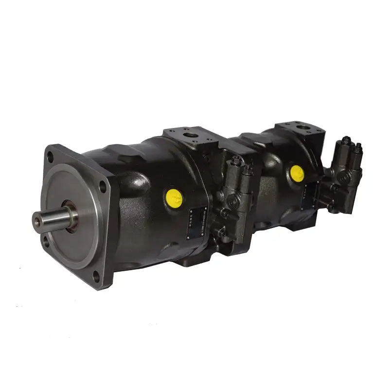
A through-drive flange lets a second JA10VSO/32 — or an external gear pump — be mounted directly on the rear of the first pump. Both pumps share one bell housing and one drive coupling, which shortens the power unit and removes a shaft alignment point.
ISO 80 to ISO 180 flanges cover second pumps from size 18 to 140, and SAE A to SAE D flanges cover gear pumps such as the 1PF2G2 and 1PF2G3. Order both pumps as a factory-assembled unit by combining the two model codes with a “+”.
Data are theoretical values taken from the JA10VSO/32 & /31 series catalogue (edition 2025-09). Dimensions, weights and controller availability may vary by size — please refer to the dimension drawing for the selected code. Jiangsu Jinrun Hydraulic Co., Ltd. reserves the right to change specifications without notice.
A11V
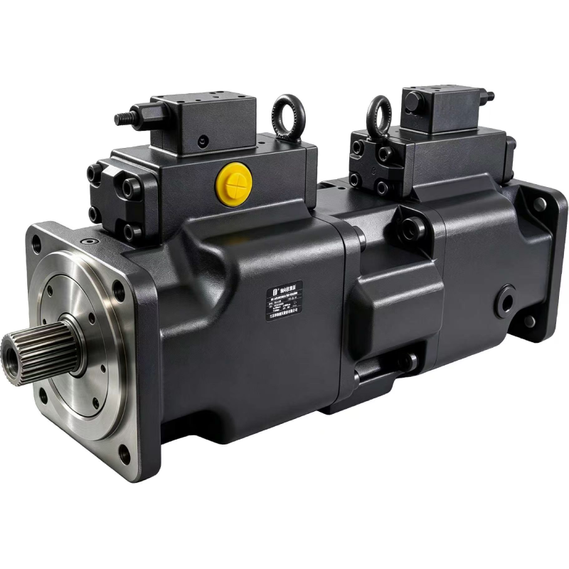
A4VLODT
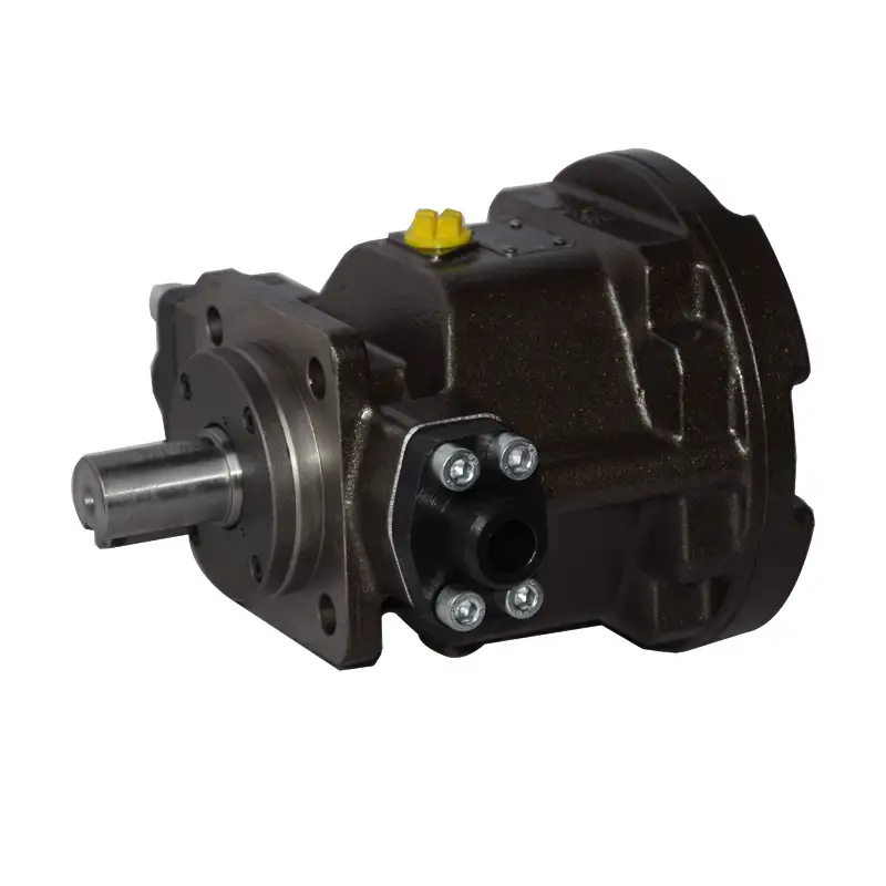
HY-M Quantitative
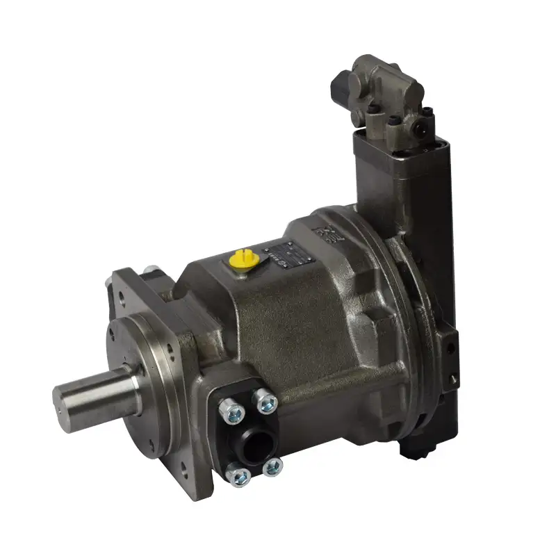
HY-P constant pressure